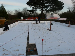
The earth between the foundations is scraped off. A good deal of what was once garden is now a foot or two higher than it was. Edging pieces—concrete L-shaped pieces internally lined with expanded polystyrene are fixed all round the outside edge. Inside, first a layer of Claymaster—a crushable polystyrene which will yield if the ground beneath should heave—is laid. On top of this goes a 100mm layer of insulation—load-bearing polystyrene.
The picture shows the first layer of insulation covering the pink tinged Claymaster (there are some sheets over at the far back right).
Then the damp proof membrane, brought up all round the sides, followed by two more layers of insulation—so there are 300 mm in all.
Into this go clips to hold the metal grid of reinforcement and reinforcement bars bent and clipped in place. On what will be the north side of the house, a plastic grid is laid which holds the pipe work of the under floor heating. It’s been agreed that although theoretically UFH is not necessary, future purchasers of the house might be worried if there was no apparent conventional heating. Placing the UFH near the bottom of the slab has two advantages—and one disadvantage.
First the amount of heat that can usefully be stored is increased, so it acts as a thermal store in its own right. Further, should we wish to bolt anything into the floor, there’s a good 3+ inches (75mm) before there’s any risk of puncturing a pipe. The disadvantage is that the response time is slow – it’ll be while before any heating effect is noticeable in the house. The pipes are all continuous—there are no joints within the slab—and are brought out to a manifold which simply acts as a place to terminate the pipes—though it could be used to zone the heating if that’s found necessary.


